
 |
 |
|
|
|
|
 05-19-2009, 12:07 AM
|
#1 |
|
My R1 eats my Vitz!!

Drives: '07 Vitz Lifty, Stick Shift Join Date: May 2007
Location: Oneida, NY
Posts: 131
|
Total running tally for this mod so far:
$9.50 for two black switches, two packs of resistors, and the little LED mount thingies $3.50 for pack of 4 switches for the clutch switch $???? for the LED light module (soon to be completed by CTScott) Also include the cost of wire, some spade connectors, soldering stuff, electrical tape, all of which I already had.
__________________
My Car Rules! |

|

|
|
05-19-2009, 10:50 AM
|
#2 | |
 ULTIMATE ULTIMATE
Drives: 09 5dr LB, 2x 08 3dr LB Join Date: Oct 2008
Location: USA, CT
Posts: 13,460
|
Quote:
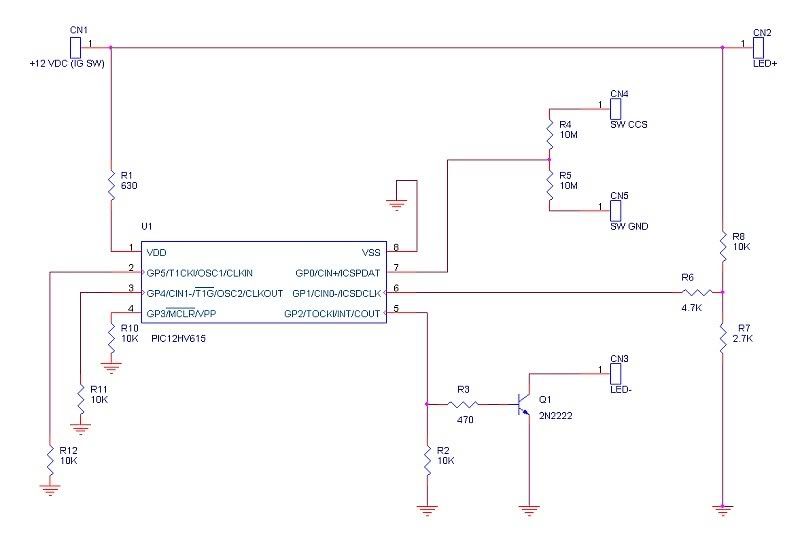
I just road tested the LED driver module on my 09. Having the indicators on the combination meter was quite handy. It took a couple of rounds of the PIC firmware to get the switch debouncing correct. I am shipping it to you today. Below are a couple of pictures (the PCB and the packaged module). I will post the schematic when I have a chance. The module hardware is fairly simple; basically a Microchip PIC12HV615 microcontroller (with built-in shunt regulator), 9 resistors, and a NPN transistor. The PIC microcontroller monitors the switch input via one of its analog to digital inputs. This lets it sense the difference between the on/off switch and the other switches. The PIC "HV" series microcontrollers have a built-in regulator which allows them to operate off of an unregulated power supply, eliminating the need for a voltage regulator.  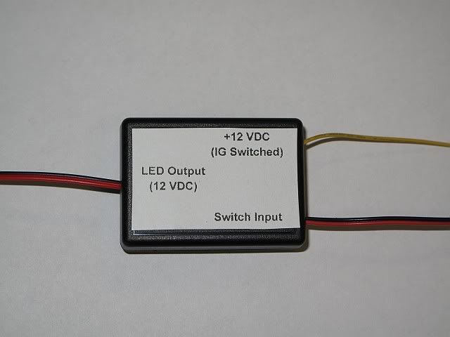 As you can see from the labels, there are three connections: 1. Switch Input - This input gets connected to the wires going from the ECM and ground to the switches (Red to CCS and Black to ground). 2. LED Output - This output drives the Cruise Control on/off LED. This supplies 12 VDC, so it is intended to drive a panel mount LED with a built-in resistor. 3. +12 VDC power input (IG switched) - This wire gets connected to an ignition switched 12 volt source. The easiest place to connect to is the pink wire on the ignition switch connector. This module will work with the DIY switches or with an OEM cruise stalk. I am shipping nickhjort's for no charge in appreciation for him being the guinea pig for this mod. If anyone else is interested in a completed module, I would probably need to charge $25 shipped to cover the parts cost (with the silly little box being the most expensive component) and labor to assemble. |
|
|
|
|
|
05-19-2009, 12:56 PM
|
#3 |
 Drives: 2008 Yaris LB Join Date: Dec 2008
Location: Murfreesboro, TN
Posts: 198
|
I'd love to see a schematic. I would be willing even to have some PCBs etched for people as drop-ins. Does this just drive the On/OFF LED? What about the SET light?
EDIT: I see you mentioned it can sense the difference between the switches, so I assume this drives both LED's. Again though, if you post the schematic I can etch actual circuit boards (instead of perfboard) for you or anyone else if there is interest. |
|
|
|
|
05-19-2009, 01:34 PM
|
#4 | |
|
ULTIMATE
Drives: 09 5dr LB, 2x 08 3dr LB Join Date: Oct 2008
Location: USA, CT
Posts: 13,460
|
Quote:
The problem with driving a SET LED, based on just the switch, is that there are too many conditions where you could press the switch, but not really be "set". Tonight I should have a chance to drop the schematic into ORCAD. If there was enough interest in the modules I figured I would do a run of boards. |
|
|
|
|
|
05-19-2009, 02:06 PM
|
#5 | |
|
Drives: 2008 Yaris LB Join Date: Dec 2008
Location: Murfreesboro, TN
Posts: 198
|
Quote:
|
|
|
|
|
|
05-19-2009, 02:13 PM
|
#6 | |
|
ULTIMATE
Drives: 09 5dr LB, 2x 08 3dr LB Join Date: Oct 2008
Location: USA, CT
Posts: 13,460
|
Quote:
I started off thinking I would use a flip flop, but you can't drive anything unless you change to a switch with a second set of contacts and you also have to maintain a high impedance to not confuse the ECM. The microcontroller is definitely overkill, but they are under $2. |
|
|
|
|
|
05-19-2009, 02:35 PM
|
#7 |

Drives: '08 5-door Join Date: Apr 2009
Location: Surrey, BC Canada
Posts: 176
|
For controlling an indicator light- has anyone considered a DPST switch for on-off? Wouldn't work for the stock cruise switch, of course, but it should be OK for the improvised setups. Too simple?
|
|
|
|
|
05-19-2009, 08:46 PM
|
#8 | |
|
ULTIMATE
Drives: 09 5dr LB, 2x 08 3dr LB Join Date: Oct 2008
Location: USA, CT
Posts: 13,460
|
Quote:
|
|
|
|
|
|
05-20-2009, 04:42 PM
|
#9 |

Drives: na Join Date: Feb 2009
Location: Netherlands
Posts: 6
|
Nice work. Please consider the fact a car power supply is really "dirty". You'll have to take bursts and surges into account. I'd add a nice big elco to VDD (at least 100uF 35V) and a 100nF 50V X5R/X7R ceramic capacitor close to the controller.
Are you measuring battery voltage at p6 ? -> Add 100nF over R7.
__________________
Citroen C2  MGF MGF 
|
|
|
|
 |
| Thread Tools | |
| Display Modes | |
|
|
 Similar Threads
|
||||
| Thread | Thread Starter | Forum | Replies | Last Post |
| DIY - 2009 Cruise Control for $10, without pulling the steering wheel and airbag | CTScott | DIY / Maintenance / Service | 307 | 04-04-2023 03:43 AM |
| DIY Cruise Control on 07-08 Yaris (step by step) | Vince87 | DIY / Maintenance / Service | 431 | 12-28-2020 01:37 AM |
| Cruise Control - Again! | CB900F2 | DIY / Maintenance / Service | 47 | 06-17-2010 06:29 PM |
| Cruise control vs MPG | YarisOwnersDad | Fuel Economy Forum | 15 | 05-29-2009 03:55 PM |
| Using Cruise control | Driver | General Yaris / Vitz Discussion | 14 | 11-09-2006 10:12 PM |


 Hybrid Mode
