
 |
 |
|
|
|
|
 05-19-2009, 12:56 PM
|
#1 |
  Drives: 2008 Yaris LB Join Date: Dec 2008
Location: Murfreesboro, TN
Posts: 198
|
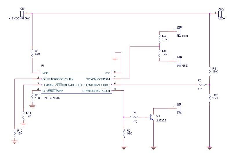
I'd love to see a schematic. I would be willing even to have some PCBs etched for people as drop-ins. Does this just drive the On/OFF LED? What about the SET light?
EDIT: I see you mentioned it can sense the difference between the switches, so I assume this drives both LED's. Again though, if you post the schematic I can etch actual circuit boards (instead of perfboard) for you or anyone else if there is interest. |

|

|
|
05-19-2009, 01:34 PM
|
#2 | |
ULTIMATE
Drives: 09 5dr LB, 2x 08 3dr LB Join Date: Oct 2008
Location: USA, CT
Posts: 13,460
|
Quote:
The problem with driving a SET LED, based on just the switch, is that there are too many conditions where you could press the switch, but not really be "set". Tonight I should have a chance to drop the schematic into ORCAD. If there was enough interest in the modules I figured I would do a run of boards. |
|
|
|
|
|
05-19-2009, 02:06 PM
|
#3 | |
|
Drives: 2008 Yaris LB Join Date: Dec 2008
Location: Murfreesboro, TN
Posts: 198
|
Quote:
|
|
|
|
|
|
05-19-2009, 02:13 PM
|
#4 | |
|
ULTIMATE
Drives: 09 5dr LB, 2x 08 3dr LB Join Date: Oct 2008
Location: USA, CT
Posts: 13,460
|
Quote:
I started off thinking I would use a flip flop, but you can't drive anything unless you change to a switch with a second set of contacts and you also have to maintain a high impedance to not confuse the ECM. The microcontroller is definitely overkill, but they are under $2. |
|
|
|
|
|
05-19-2009, 02:35 PM
|
#5 |

Drives: '08 5-door Join Date: Apr 2009
Location: Surrey, BC Canada
Posts: 176
|
For controlling an indicator light- has anyone considered a DPST switch for on-off? Wouldn't work for the stock cruise switch, of course, but it should be OK for the improvised setups. Too simple?
|
|
|
|
|
05-19-2009, 03:56 PM
|
#6 | |
|
ULTIMATE
Drives: 09 5dr LB, 2x 08 3dr LB Join Date: Oct 2008
Location: USA, CT
Posts: 13,460
|
Quote:
|
|
|
|
|
|
05-19-2009, 06:14 PM
|
#7 | |
|
Drives: '08 5-door Join Date: Apr 2009
Location: Surrey, BC Canada
Posts: 176
|
Quote:
If someone can come up with a tidy module to make this work, it could be a minor cottage industry. It should work with the OEM switch installations, as well as the improvised ones. |
|
|
|
|
|
05-19-2009, 08:46 PM
|
#8 | |
|
ULTIMATE
Drives: 09 5dr LB, 2x 08 3dr LB Join Date: Oct 2008
Location: USA, CT
Posts: 13,460
|
Quote:
|
|
|
|
|
|
05-20-2009, 04:42 PM
|
#9 |

Drives: na Join Date: Feb 2009
Location: Netherlands
Posts: 6
|
Nice work. Please consider the fact a car power supply is really "dirty". You'll have to take bursts and surges into account. I'd add a nice big elco to VDD (at least 100uF 35V) and a 100nF 50V X5R/X7R ceramic capacitor close to the controller.
Are you measuring battery voltage at p6 ? -> Add 100nF over R7.
__________________
Citroen C2  MGF MGF 
|
|
|
|
 |
| Thread Tools | |
| Display Modes | |
|
|
 Similar Threads
|
||||
| Thread | Thread Starter | Forum | Replies | Last Post |
| DIY - 2009 Cruise Control for $10, without pulling the steering wheel and airbag | CTScott | DIY / Maintenance / Service | 307 | 04-04-2023 03:43 AM |
| DIY Cruise Control on 07-08 Yaris (step by step) | Vince87 | DIY / Maintenance / Service | 431 | 12-28-2020 01:37 AM |
| Cruise Control - Again! | CB900F2 | DIY / Maintenance / Service | 47 | 06-17-2010 06:29 PM |
| Cruise control vs MPG | YarisOwnersDad | Fuel Economy Forum | 15 | 05-29-2009 03:55 PM |
| Using Cruise control | Driver | General Yaris / Vitz Discussion | 14 | 11-09-2006 10:12 PM |


 Hybrid Mode
