
 |
 |
|
|
|
|
 04-27-2009, 10:10 AM
|
#1 |
 ULTIMATE ULTIMATE
Drives: 09 5dr LB, 2x 08 3dr LB Join Date: Oct 2008
Location: USA, CT
Posts: 13,460
|
The more I look at this issue, I think that the switch is the issue. The OEM stalk switch is just a switch, connecting pins 3 and 4 on D4. The OEM console switch has the switch isolated from the leds. In the picture of the guts of your switch on that DIY, the switch LED is part of the switch circuit. I think that is what is causing the headaches.
I would modify the switch as follows: 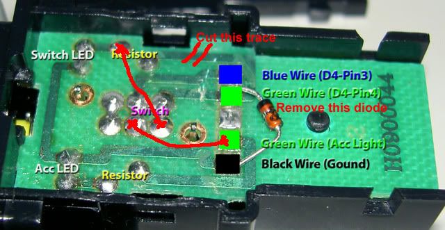 1. Cut the marked trace. 2. Remove the diode. 3. Solder the two jumper wires as indicated. 4. If the pads for the switch are bridged together (where the word "switch" is between two sets of 3 pads), separate them. The switch is a dual pole switch, which allows it to separately switch the two circuits. |

|

|
|
04-27-2009, 11:17 AM
|
#2 | |
 
|
Quote:
thanks.. |
|
|
|
|
|
04-27-2009, 11:24 AM
|
#3 | |
|
ULTIMATE
Drives: 09 5dr LB, 2x 08 3dr LB Join Date: Oct 2008
Location: USA, CT
Posts: 13,460
|
Quote:
|
|
|
|
|
|
04-27-2009, 09:32 PM
|
#4 |
|
|
oooooohhh!!! Sorry! I was at school and didnt see there was a picture there... Im understanding it more. my only questions are:
How do I open the switch to see what the picture shows? where/what is the diode? what are the two jumper cables and where do I solder them? and what do u mean by "If the pads for the switch are bridged together (where the word "switch" is between two sets of 3 pads), separate them."? sorry again and thanks... |
|
|
|
|
04-27-2009, 11:21 PM
|
#5 | |
|
ULTIMATE
Drives: 09 5dr LB, 2x 08 3dr LB Join Date: Oct 2008
Location: USA, CT
Posts: 13,460
|
Quote:
To open it, there should be two tabs about 3/4" above the connector that can be pressed in to pull the connector and circuit board away from the housing. The diode is the orange and black device. The "jumpers" are two pieces of insulated wire that you will need to strip the ends of a solder them between the indicated endpoints. By bridged I mean connected. They may have a silver solder blob (silver) connecting them or there may be a trace (shiny green) connecting them. |
|
|
|
|
 |
| Thread Tools | |
| Display Modes | |
|
|
 Similar Threads
|
||||
| Thread | Thread Starter | Forum | Replies | Last Post |
| Speakers wires : how to identify + and - ? | hystria | In Car Entertainment + Electronics (audio / video / alarm) | 23 | 05-27-2017 10:43 PM |
| DIY: LED side mirror installation | eTiMaGo | DIY / Maintenance / Service | 85 | 06-24-2011 11:48 AM |
| Installing a remote starter without cutting factory wires? | yaris08ce | In Car Entertainment + Electronics (audio / video / alarm) | 36 | 04-23-2009 08:59 PM |
| Ground Wires | dngz | Performance Modifications | 8 | 11-26-2006 11:54 PM |
| Q about Routing wires to the engine compartment | W.A.S.P | In Car Entertainment + Electronics (audio / video / alarm) | 10 | 11-01-2006 07:36 PM |


 Hybrid Mode
